Lock Wiring Diagram
Wiring Diagram To Maglock Iei Keypad Wiring Diagram Schemas
This video provides the detailed instructions with wiring diagram for the installation of a custom gate magnetic lock system including a complete battery bac.

Maglock Wiring Diagram Free Wiring Diagram
The wiring diagram for magnetic door lock should be as follows: If the electric magnetic door lock is designed with 12VDC/24VDC interchangeable, for instance, TOPLOCK's magnetic locks, you need to short-circuit some internal circuitry to achieve it. Operations:

Door Contact Wiring Diagram
Learning hub Access control components AC Cables and Wiring Diagram Access Control: Wiring Diagram and Cables Explained What does the wiring diagram for access control system look like? Find out the different types of cables and wires that your security system needs. Guide Downloads Kisi Access Control Share this article
Empower Grease Coherent biometric door lock Head Decimal Grand delusion
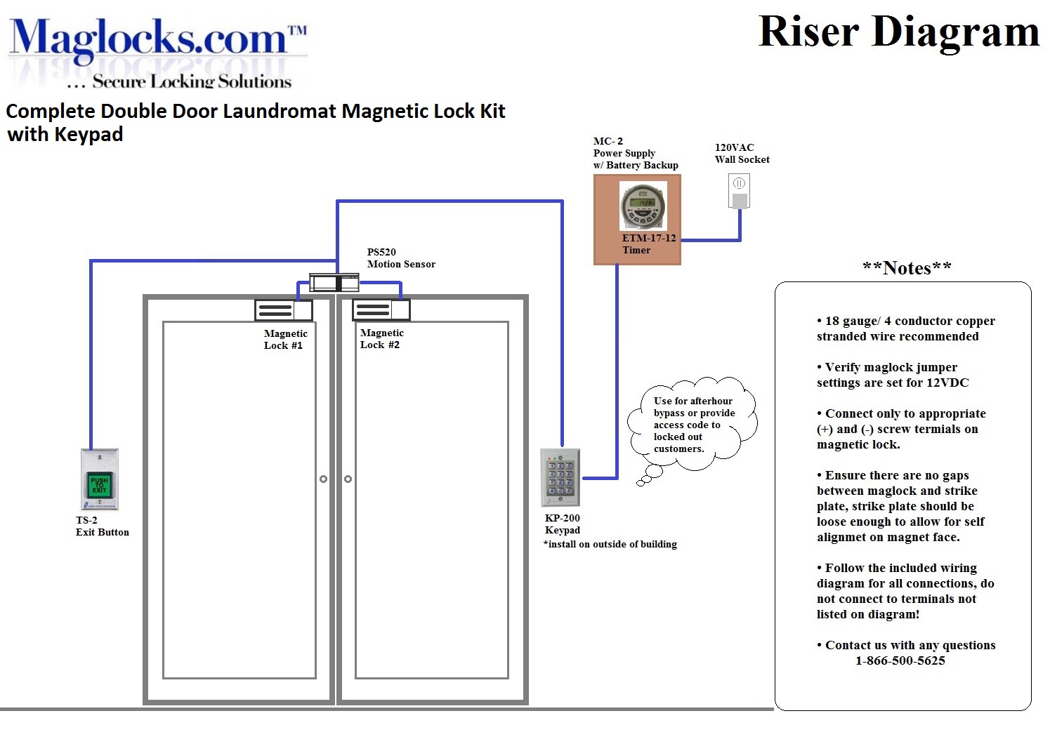
Magnetic lock systems can be very complicated if a wiring diagram is not provided. When purchasing a magnetic lock kit be sure a step by step wiring diagram is included. Most magnetic lock kits on the market today do not include a step by step wiring diagram, making installation a "guess and check" process. In fact, about 75% of magnetic lock.
lock wiring diagram
How It Works When the electromagnet is powered, a current passing through the electromagnet creates a magnetic flux that causes the armature plate to attract to the electromagnet ⇒ a locking action When the electromagnet is NOT powered, there is no a magnetic flux, armature plate does NOT attract to the electromagnet ⇒ a unlocking action

Door Lock Circuit Diagram Wiring Diagram
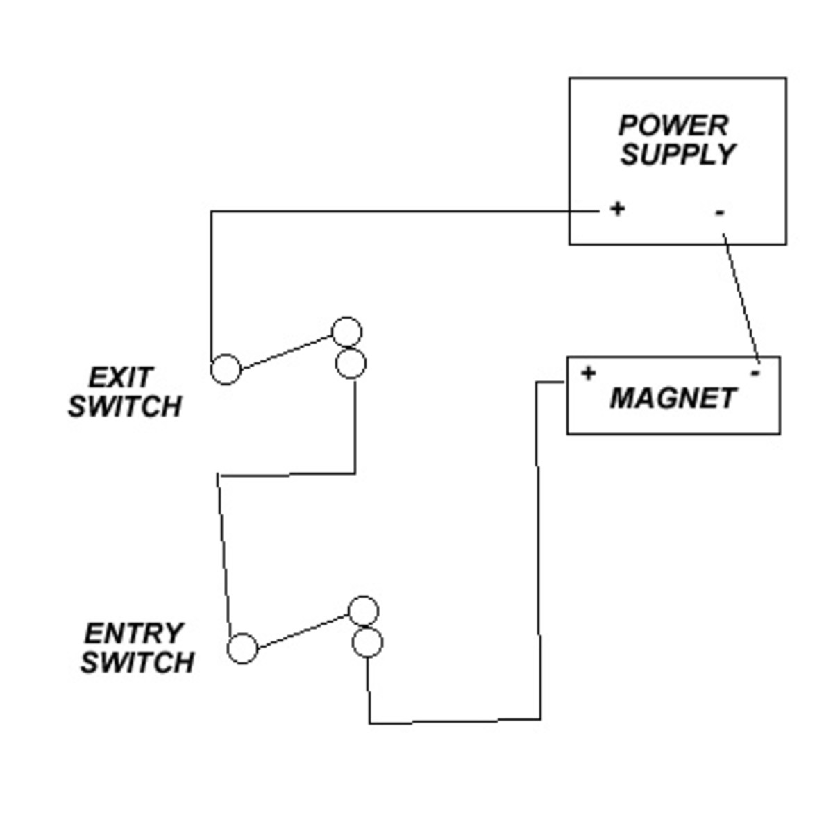
Wiring the Electromagnetic Locking System. In the simple diagram above, you can see that the electricity travels in an unbroken loop. It starts at the "+" (positive) terminal of the power supply, travels through the exit and entry switches, into the positive terminal of the magnetic lock, and out through the negative (-) terminal of the mag back in through the negative terminal of the power.

RFID Access Control Electric Door Lock ID Password Safty Entry System eBay
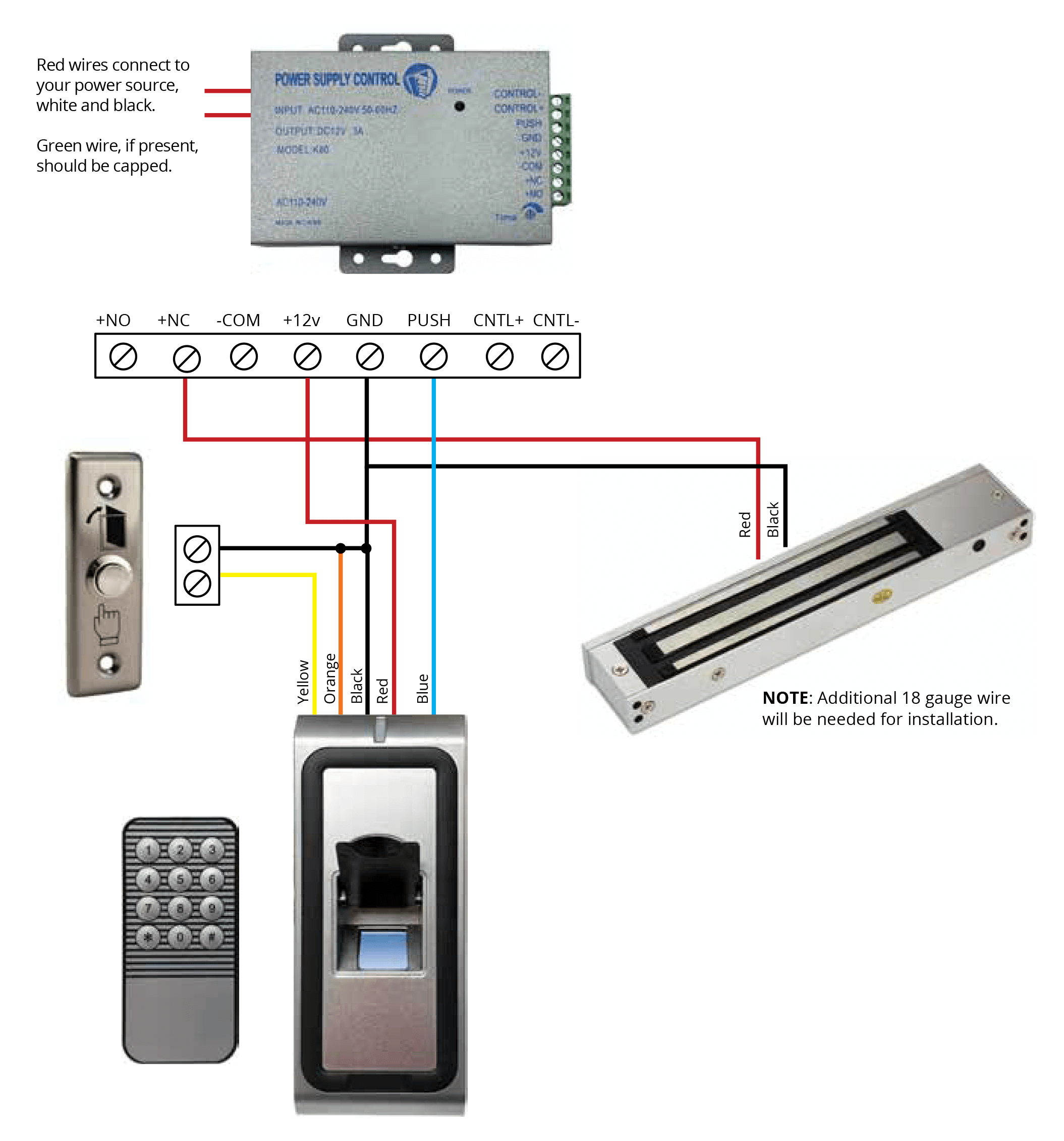
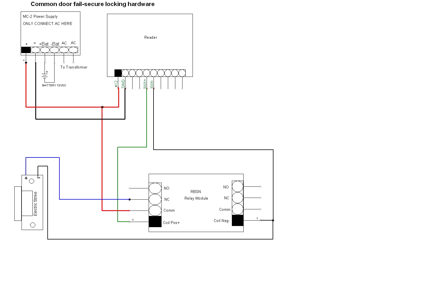
Learn how to wire a Schlage CT5000 standalone offline controller with a MTK15 multi-technology reader and a magnetic lock in this detailed diagram. This document provides step-by-step instructions, color-coded wires, and safety tips for a successful installation.
Wiring Diagram For Maglock
INSTALLATION INSTRUCTIONS E600 SERIES MAGNETIC LOCK The E600 Series magnetic lock is mounted to the underside of the header, on the stop side of the door. An inswing mounting kit (optional) can be used when mounting on the hinge side of the door. Interlocking Mounting Plate Quick Mount Interlocking Mounting Assembly Mounting Screws Armature Frame
Wiring Diagram For Maglock
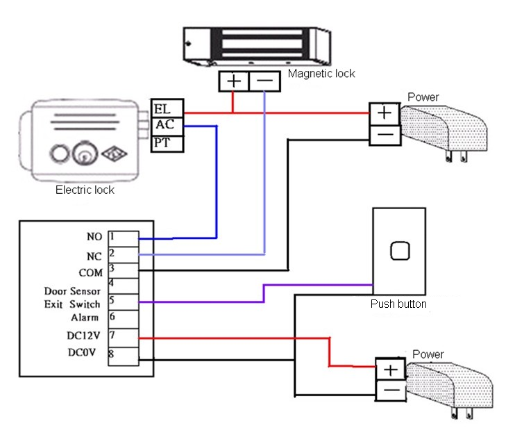
A magnetic lock wiring diagram is a drawing that shows how to wire a magnetic lock to the electric circuit of a building. It is usually included with the purchase of a magnetic lock or can be downloaded from the manufacturer's website. The diagram shows the locations of the power and ground wires, as well as the wires from the magnetic lock.
Basic Door Lock System HubPages
0:00 / 7:37 Mag-lock wiring in three minutes. Jaytee Mapp 93 subscribers Subscribe Subscribed 69 Share Save 12K views 5 years ago How to wire a magnetic lock with, backup battery, exit.

Lock 8011xlc Wiring Diagram
A wiring diagram or schematic is a visual representation of the connections and layout of an electrical system. It shows how the electrical wires are interconnected and can also show where and how components are connected to the system.
Lock Wiring Diagram
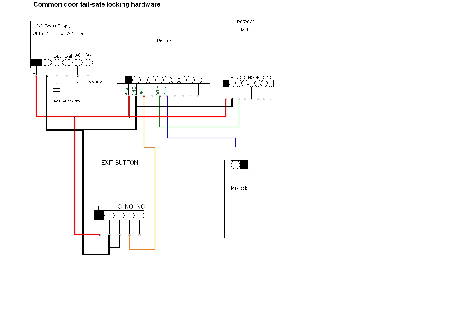
Below is the magnetic lock wiring diagram with multiple access control devices. What else should you know about the magnetic gate lock? Since electromagnetic locks are driven by electric power to operate, they only have the fail-safe mode: to unlock when power is off. There's no fail-secure magnetic lock (which means to lock when power is off.

Access Control Cables and Wiring Diagram Kisi
Route the power supply connecting wire through the door frame and into the wire access hole in the top of the magnet housing. Connecting wire should be of sufficient gauge for the lock being installed and the distance being run. See table for current draw specifications and wiring gauge chart. Installation Instructions Pre-Installation.

door switch wiring diagram
THE MAGNETIC LOCK IS DESIGNED TO MOUNT TO THE DOOR FRAME ON THE STOP SIDE OF THE DOOR IN A TYPICAL OUTSWINGING DOOR INSTALLATION,(SEE PAGE 2 FOR INSWINGING DOOR INSTALLATION). SUFFICIENT HEADER SPACE MUST BE AVAILABLE TO MOUNT THE MAGNETIC LOCK TO INSURE A SAFE AND SECURE INSTALLATION. 1.

Wiring Diagram For Door Lock
Magnetic Bond Sensor Door Position Switch Tri-Color LED Red or Green Both on = Yellow SPST, No, Dry SPDT, Dry 20 mA 40 mA All switches rated @ 250 mA @ 30 VDC AVAILABLE OPTIONS ELECTRICAL INSTALLATION IMPORTANT NOTES 1. Use jacketed cable for all wire runs. Refer to the SDC wire gauge chart for proper lock power wire size (18 AWG gauge minimum). 2.

Door Contact Wiring Diagram Free Wiring Diagram
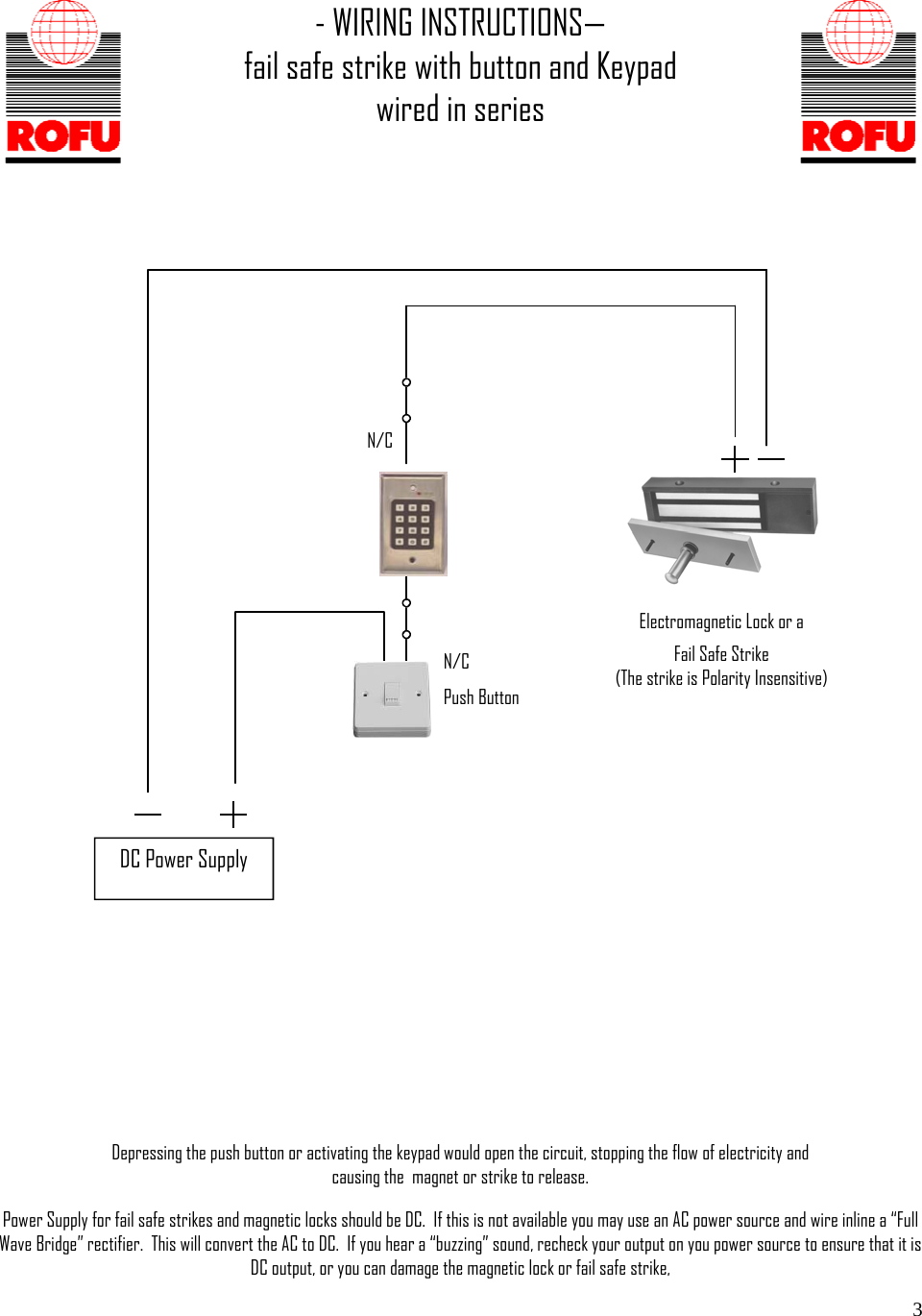
Elock magnetic locks, which are installed in doors for added security, work by activating or deactivating a set of locking pins when activated. But, although theoretically simple to install, getting them up and running requires an understanding of electrical wiring and installation.
